SparkFun RedBoard Qwiic

Description Links Connect diagram Attachments
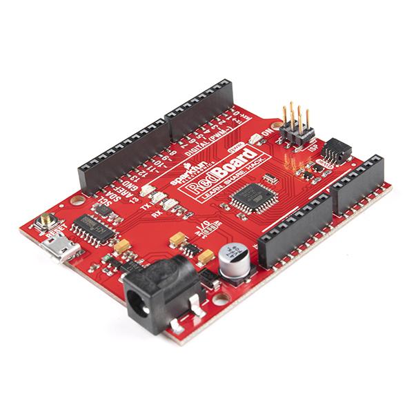
Not only does the RedBoard Qwiic feature a Qwiic Connector, it also boasts an AP2112 voltage regulator. This robust 3.3V regulator provides more power, allowing for the daisy chaining of multiple Qwiic boards and sensors, sourcing up to 600mA of current. The CH340C Serial-USB converter IC supports the micro USB connector, reducing the need for manual driver installation. Solder jumpers have been added to the board, providing the option to disconnect the logic level converters from the A4 and A5 pins. The voltage level jumpers can switch the RedBoard Qwiic from a 3.3V device to a 5V device.
The RedBoard Qwiic can be programmed over a USB Micro-B cable using the Arduino IDE. It features 20 digital I/O pins, 6 PWM pins, UART, SPI and external interrupts. The SDA, SCL and IOREF pins are broken out, ensuring future shield compatibility. Power can be supplied over USB or through the barrel jack, with the on-board power regulator handling anything from 7 to 15VDC.
The Qwiic Connect System is an ecosystem of I2C sensors, actuators, shields and cables that streamline prototyping and reduce errors. All Qwiic-enabled boards use a common 1mm pitch, 4-pin JST connector. This minimises required PCB space, and the polarised connections prevent incorrect hook up.
Features of the RedBoard Qwiic include an ATmega328 microcontroller with Optiboot (UNO) Bootloader, CH340C Serial-USB Converter, AP2112 Voltage Regulator, A4/A5 Jumpers, 3.3V to 5V Voltage Level Jumper, 1 Qwiic Connector, 20 Digital I/O Pins (6 PWM Outputs and 6 Analog Inputs), ISP Header, 32k Flash Memory, 16MHz Clock Speed, all SMD Construction, R3 Shield Compatibility, and an improved Reset Button.
Resources available for the RedBoard Qwiic include a schematic, Eagle Files, a hookup guide, instructions on how to install CH340C Drivers, an Arduino Buying Guide, Arduino IDE Download, Qwiic Page, GitHub, and a comparison of SparkFun RedBoards.
Properties
| Brand | Sparkfun |
| Model | DEV-15123 |
| More info | RedBoard Qwiic Hookup Guide - learn.sparkfun.com |
| Connector | Qwiic |
| Voltage | 3,3 V - 5 V |
| Number of I / O | 20 |
| Input voltage | 7 V - 15 V |
| PWM | 6 |
| Analoog I / O | 6 |
| Flash memory | 32 KB |
| Stroom per I/O | 20 mA |
| Microcontroller | ATmega328 With Optiboot (UNO) Bootloader |
| Clock speed | 16 MHz |
| EEPROM | 1 KB |
| SRAM | 2 KB |
Alternative products
- Opencircuit Arduino Uno R3 - clone € 11,25 View product
- In stock Arduino® UNO R4 Minima € 21,50 View product
- ATmega328 Arduino UNO - Velleman € 20,40 View product
- Arduino Uno Rev3 SMD € 23,50 View product
- Arduino Uno Rev3 € 24,60 View product
- Arduino® UNO R4 WiFi € 31,55 View product
- SparkFun RedBoard Turbo - SAMD21 Development Board € 27,75 View product
- Cytron Maker UNO: Simplifying Arduino for education € 10,50 View product
- In stock Opencircuit Arduino UNO R4 Minima - clone € 12,85 View product
- In stock DFRobot DFRduino UNO R3 - Arduino Compatible € 16,- View product
- Arduino Uno WiFi Rev2 € 51,30 View product
- DFRobot Bluno - An Arduino UNO Compatible Bluetooth 4.0 (BLE) Controller € 30,50 View product
- SparkFun RedBoard Artemis € 30,50 View product
- SparkFun Arduino UNO R4 WiFi Qwiic Kit € 141,80 View product
- Cytron Maker UNO X € 10,25 View product
- In stock Opencircuit Arduino UNO R4 WiFi - clone € 26,30 View product
Related products
- In stock Opencircuit Micro USB cable 50 cm blue € 1,50 View product
- In stock Opencircuit Micro USB cable 100cm blue - 30AWG € 3,20 View product
- Adafruit USB micro B Cable with LEDs - Blue and Green € 8,75 View product
- Adafruit USB micro B Cable with LEDs - Blue and Red € 8,85 View product
- DFRobot Reversible USB to microUSB 2.0 Cable with Antioxidant Connectors € 4,- View product
Customer questions
Customer Reviews
 Emiel Planting
Suggested products
- Opencircuit Arduino Uno R3 - clone € 11,25 View product
- Opencircuit 6-DOF (gyroscope and accelerometer) module (GY-521) € 3,40 View product
- In stock Opencircuit Infrared receiver and remote control kit € 3,20 View product
- In stock Opencircuit Male-Female 20 cm band cable 40 pieces € 1,50 View product
- Opencircuit ULN2003 stepper motor driver module € 2,10 View product
- In stock Opencircuit HC-SR04 Ultrasonic distance detection module € 2,15 View product
- In stock Opencircuit 5V Relay module 2 channels € 2,15 View product
- Opencircuit PIR motion detection module € 1,85 View product
- Pololu Zumo Robot for Arduino, v1.2 (Assembled with 75:1 HP Motors) € 84,65 View product
- Opencircuit Gift card View product
- In stock Kitronik 2xAAA Battery Cage with JST Connector € 1,45 View product
- Kitronik 2x AAA Battery Box with Switch and JST Connector € 2,15 View product
- In stock Opencircuit ZVP3306A Power MOSFET, P Channel, 60V, 160mA, 14 Ohms, E Line - Through Hole € 2,70 View product
- Pololu 3pi+ 32U4 Robot - Turtle Edition (75:1 LP Motors) - Assembled € 224,65 View product
- In stock PLA Filament Marble light - 1.75 - 1kg - Devil Design € 28,60 View product
- In stock Sparkfun Alligator Test Leads - Multicolored (10 Pack) € 6,50 View product
- In stock Sparkfun Teensy Stackable Header Kit (Extended) € 2,90 View product
- In stock Sparkfun RJ45 8-Pin Connector € 2,50 View product
- In stock Sparkfun Voltage Regulator - 3.3V € 2,75 View product
- In stock Sparkfun Qwiic JST Connector - SMD 4-Pin (Vertical) € 1,45 View product
- In stock Sparkfun Capacitor Ceramic 0.1uF € 1,20 View product
- In stock Sparkfun Mini Power Switch - SPDT € 2,30 View product
- In stock Sparkfun Conductive Thread Bobbin - 30ft (Stainless Steel) € 7,25 View product
- In stock Sparkfun Rotary Encoder - Illuminated (RGB) € 7,20 View product
- In stock SparkFun Micro 6DoF IMU Breakout - BMI270 (Qwiic) € 21,75 View product
- In stock Sparkfun Copper Tape - Conductive Adhesive, 5mm - 15 meter € 7,75 View product
- In stock Sparkfun Clear Plastic Knob € 1,75 View product
- Deal In stock -9 % Sparkfun Silicone Electrical Tape - Pack of 10 Strips € 8,65 € 7,85 View product
- In stock Sparkfun Resistor Lead Bending Tool € 11,- View product
- In stock Sparkfun Hobby Motor - Gear € 3,50 View product


