DSMR Logger V4 (Smart Meter Reader)
Placed onTelegram received
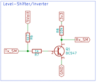
The telegram is sent by the Smart Meter via pin 5 of the RJ12 connector with an inverted 5volt TTL logic. For the ESP8266, this signal must be inverted (back) as well as made suitable for 3v3 logic of the ESP8266.
 Lever-Shifter/Inverter Circuit
 At rest, R6 will be the Base of Q1 “high” pulling, leaving Q1 “Closed” becomes and the Collector, and with it Rx_SM “low" will be. If Tx_SM “low” is will the Base of Q1 also “low” will be and will be Q1 “Open" go stand. The Collector and with it Rx_SM will be pulled to 3v3 by R8. Rx_SM is then “high”. Does Tx_SM come with a “high” signal in, then the Base of Q1 will also “high" become. This causes Q1 to conduct and the Collector together with Rx_SM “low" become.
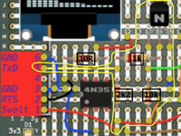
 Lever-Shifter / Inverter on the 1of!-Proto board
 Above you can see how that part of the schematic looks on it 1of!-Proto plate looks.


