DSMR Logger V4 (Smart Meter Reader)

Placed on

Putting It All Together

To complete the schematic of the new DSMR logger, the basic circuit of the ESP8266 still needs to be added (see my post about the 1or!-ESP12). This basic circuit consists of the ESP-12, the 3v3 power supply, a Program Interface and the circuitry around the Reset and Flash buttons.

The complete schematic for the DSMR logger V4: The complete schematic for the DSMR logger V4:
And below is a picture of the prototype as I see it on the 1or! signs made and tested.
My Prototype 
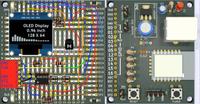
My Prototype "life" in the fuse box!
Current Page 6. Putting It All Together 1. Introduction 2. data request circuit 3. Process telegram 4. I2C interface 5. ADC interface 6. Putting It All Together 7. A beautiful packaging Posted by Website Willem Aandewiel (1955) has a background in electronics and digital techniques. However, most of his working life he has worked in automation where he has worked in just about all disciplines from programmer to project leader and project manager. Willem was one of the first Dutchmen with a micro-computer (KIM-1, 1976) at a time when the PC had yet to be invented. Nowadays he is mainly concerned with the design and production of small electronic circuits with microprocessors. His 'mission in life' is to make people enthusiastic about making their own electronic circuits, microcomputers and programming.

Comments

Webwinkelkeur Kiyoh Trustpilot Opencircuit