DSMR Logger V4 (Smart Meter Reader)

Placed on

data request circuit

For the "high" and "lowmaking the Data request pin of the Smart Meter I have tried different variants. With a combination of one or two transistors and/or MosFets I couldn't get it to work stably. In the end it is one optocoupler become.

Below is the schematic for the Data Request functionality:
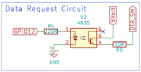
data request circuit data request circuit

The circuit is controlled from GPIO12 of the ESP8266 and ensures that at a “high” signal goes to the LED in the opto-coupler to burn.

This will cause the transistor “Close” (it will conduct) so that the 5Volt on the collector (pin5) ends up directly on the emitter (pin4) (it becomes “high”). This will also make DTR_SM “high” and the Smart Meter will send a telegram.
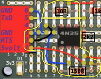
DTR circuit on the 1of!-Proto board DTR circuit on the 1of!-Proto board
Current Page 2. data request circuit 1. Introduction 2. data request circuit 3. Process telegram 4. I2C interface 5. ADC interface 6. Putting It All Together 7. A beautiful packaging Posted by Website Willem Aandewiel (1955) has a background in electronics and digital techniques. However, most of his working life he has worked in automation where he has worked in just about all disciplines from programmer to project leader and project manager. Willem was one of the first Dutchmen with a micro-computer (KIM-1, 1976) at a time when the PC had yet to be invented. Nowadays he is mainly concerned with the design and production of small electronic circuits with microprocessors. His 'mission in life' is to make people enthusiastic about making their own electronic circuits, microcomputers and programming.

Comments

Webwinkelkeur Kiyoh Trustpilot Opencircuit