DONOFF iot light dimmer
Placed onBuild a DONOFF device
Warning:
any circuit that works with mains voltages is inherently dangerous and you should NEVER work with mains voltages unless you know exactly what you are doing. The DONOFF circuit is purely theoretical and offers no isolation or safety functions! Therefore, without modification, it is not a safe circuit, or has practical applications beyond serving as a proof-of-concept.
any circuit that works with mains voltages is inherently dangerous and you should NEVER work with mains voltages unless you know exactly what you are doing. The DONOFF circuit is purely theoretical and offers no isolation or safety functions! Therefore, without modification, it is not a safe circuit, or has practical applications beyond serving as a proof-of-concept.
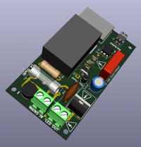
DONOFF dimmer PCB
If you're still reading this, I have one more warning: whatever you do, don't build this circuit on a breadboard! You can build it on an experiment board (use a board with through-plated pads) and make sure you have good soldering.By far the best way is to use a specially designed printed circuit board (PCB) as shown below.
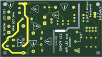
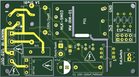
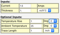
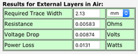
The circuit board is designed using KiCad 5.0. I had a first series made by PCBWay. The standard copper layer used by PCBWay is 1 oz/ft2 and according to the Online Trace Width Calculator the trace width for the High Power (HP) traces should then be about 2mm.
Bill Of Material (BOM)
| # | Element | Description | Price |
|---|---|---|---|
| 1 | DONOFF PCB | © by Willem Aandewiel | 6,00 |
| 1 | B420C1500 (Round) | D1 – Bridge rectifier 1.5A 420VAC | 0,25 |
| 1 | 1N4007 | D2 – Diode 1000V 1A | 0,05 |
| 1 | 1N 5352BG US | D3 – Zener diode 017AA 15V 5W | 0,25 |
| 1 | 4N 35 | U1 – Optocoupler | 0,30 |
| 1 | 2 Watt Metal 150K | R4 – Metallic film resistor 2W, 5% 150K-ohm | 0,15 |
| 2 | Metallic 220 ohms | R3,R6 – Metallic film resistor 1/2W 220 ohm | 0,20 |
| 1 | Metal 6k8 ohms | R7 – Metallic film resistor 1/4W 6800 ohm | 0,10 |
| 2 | Metal 10K ohms | R2,R5 – Metallic film resistor 1/4W 10K-ohm | 0,20 |
| 1 | VDR-0.6 460 | RV1 – Varistor Rm 7.5mm 0.6W 460VAC = JVR14N751K | 0,30 |
| 1 | RUBY 100PX47MT78 | C2 – Elco Radial 47 uF RM 3.5 105*C 2000H 20% | 0,30 |
| 1 | MMK 220N 400 | C1 – Film Capacitor 220nF 400V 100*C | 0,30 |
| 2 | LAKL 1.5 2 5.08 | J1,J3 – Phoenix Screw terminal 2-pole RM 5.08mm 90* | 1,25 |
| 1 | LAKL 2 2.54 | J2 – Phoenix Screw terminal 2-pole RM 2.54mm 90* | 0,60 |
| 1 | KTR 1.0A | Fuse 5x20mm Slow Blow 1,000A | 0,55 |
| 1 | PL 112000 | F1 – Fuse holder 5x20mm max 6.3A/250V | 0,30 |
| 1 | AC to 3.3v DC | PS1 – Hi-Link HLK-5M03 or Mean well IRM-01 | 7,40 |
| 1 | ESP-01 | U2 – ESP8266 module ESP-01 black edition (1MB) | 5,90 |
Putting it all together
Building a DONOFF is easiest if you do the following steps in order.Make sure you have all the right parts before you start!
Step 1
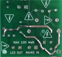
The High-Power traces on the PCB are only 1.5 mm wide. To meet the rated current of ~1 amp I omitted the solder mask on these traces. This makes it possible to cover them with a layer of solder, which increases the maximum current. It is imperative that you do too!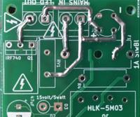
Step 2
Solder the lowest parts first. These are R1, R2, R5, D1 and U1.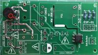
Make sure that D1 and U1 are placed correctly. The “+” of D1 opposite the markings on the PCB. U1 has a small mark (dot) next to pin 1 or a small groove on the side where pin 1 is. Align pin 1 with the 1 on the silkscreen.
The resistors have no polarity, so it doesn't matter how you place them.
The resistors have no polarity, so it doesn't matter how you place them.
Step 3
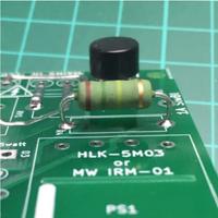
Place R4 but make sure you fix it slightly above the PCB (see picture), because this is a part that gives off a lot of heat. The more air that surrounds R4, the better it can dissipate this heat. The temperature of R4 rises about 15°C above the ambient temperature!
Step 4
Now place the diode D2 and the resistors R3, R6 and R7 upright.
Step 4
Now place the diode D2 and the resistors R3, R6 and R7 upright.
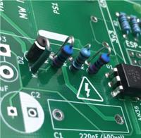
Try to place them in such a way that the chance of them making contact with other parts is as small as possible. The polarity of D2 is important! The end on the side of the white stripe on D2 connects to the square pad on the PCB.
It is always a good idea to insulate the connections with shrink tubing.
It is always a good idea to insulate the connections with shrink tubing.
Step 5
Solder D3 vertically to the PCB. Polarity is important!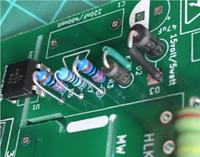
The connection on the side of the white stripe on D3 must be connected to the square path. Here too it is best to provide the long connection with a piece of shrink tubing!
Step 6
Now place F1 (fuse holder), RV1 (varistor) and C2. Make sure the white stripe on C2 (–) is on the side of the white semicircle on the silkscreen!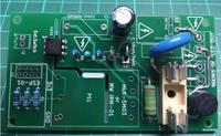
Step 7
Solder Q1 with the metal 'back' facing C2. To lower the profile of the DONOFF dimmer you can bend Q1 slightly towards C2. And again, some shrink tubing over Q1 will reduce the chance of a short circuit and reduce the chance of you being electrocuted!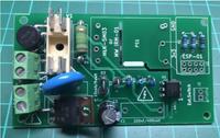
Step 8
Now place the 2×4 header for the ESP-01 and the three screw terminals for Mains-In, LED-Out and the Ext.Switch.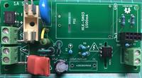
Step 9
Finally, solder C1 and PS1 to the PCB.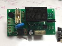
You are done!
The DONOFF is ready to plug the ESP-01 into the 2×4 header.
The DONOFF is ready to plug the ESP-01 into the 2×4 header.
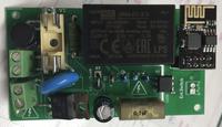
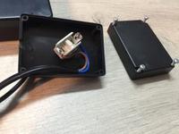
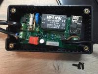
As I mentioned earlier, this project is very dangerous because of the high voltages and the many exposed parts that carry this high voltage. Therefore it is necessary to set the DONOFF dimmer a suitable housing before you connect it to the mains!
Rapping it all up
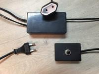
I cut an extension cord to 1/3 and then connected the plug to MAINS IN and connected the contra plug to LED OUT.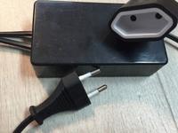
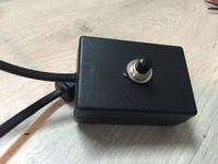
Add an External switch
The external switch connection is isolated from the mains and connected to the low voltage part (3v3) of DONOFF, so it does not matter much what kind of cord you use to connect the external switch.Since this example is a foot switch, I opted for a robust switch and housing.