DONOFF iot light dimmer
Placed onThe Electronics
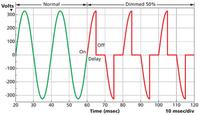
You can find hundreds of posts on the internet explaining how to dim a lamp using a triac by cutting off part of the sine wave.Some describe how to truncate the sinus at the beginning (Leading-Edge)
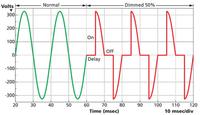
Others describe how to truncate the sinus at the end (Trailing-Edge) and what the advantages and disadvantages of both methods are.
Elegant and simple as both solutions are, they only work for resistive loads (aka incandescent bulbs). However, it is becoming increasingly difficult to buy light bulbs, at least in the Netherlands, and in the near future you will only be able to buy LED lamps. The problem with LED bulbs is that you can't dim them using the methods described above. Dimmable LED lamps can only be dimmed with a technique called Pulse Wide Modulation (PWM). With PWM you switch the voltage on and off for a short time at a (relatively) high frequency.

DONOFF therefore uses PWM to dim the (dimmable!) LED lamp, but PWM also works excellently with incandescent lamps and even with halogen lamps!
A schematic for a mains PWM dimmer that you will find all over the internet has been designed by Ton Giesberts Countless improvements have been devised on that design, such as that of diy_block For the design of the DONOFF circuit I have used this design, and the numerous improvements to it, as a basis.
DONOFF uses a MOSFET transistor to switch the voltage on and off. A MOSFET is (simplified) an on/off switch. The switch is closed by applying a positive voltage (Vin > 10 Volt) to the Gate. If you remove the Gate voltage (Vin = 0 Volt), the switch opens. When the switch is open (Vin = 0 Volt) the internal resistance between the Drain and the Source is infinite (simplified). If the switch is closed (Vin > 10 Volt) then the internal resistance between the Drain and the Source is 0 ohm (simplified again!). In both states, the MOSFET will not draw any power and the temperature of the MOSFET will therefore not increase. However, it is important that the transition between open and closed lasts as short as possible, because power is indeed absorbed by the MOSFET during that period.
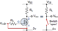 MOSFET "Open"
 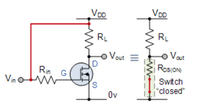 MOSFET "Closed"
 Before continuing, please read the warning below!
The full schedule:
Warning
Do not copy this design! Chances are the design will kill you and burn your house down while using it. Then the circuit will explode!
I do not make a joke! This project uses lethal voltages and you should only build it if you are a qualified electrical engineer. If you decide to rebuild it anyway, it is your responsibility to take the necessary precautions. I do not take any responsibility for your actions in carrying it out. In fact, I am NOT a qualified electrical engineer, so I make no guarantees as to the design or suitability of this design for your purposes.
The full schedule:
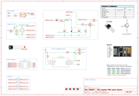
The design generally consists of five subsystems. I will briefly explain each subsystem.


