









3D Clock
Placed onSaw printed circuit boards
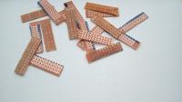 Sawn printed circuit boards
 Now it's time to make all the lighting for the 3D printed segments.
Saw 28 smaller plates of about 3x13 holes from an experimental circuit board. See image above
For the : in the middle you also have to make 2 times a 4x4 holes PCB.
Soldering
Each segment will contain 2 5050 SMD LEDs and 2 220 ohm resistors. Solder these according to the image below, the perforated printed circuit boards are not actually intended for smd components, but with a little fiddling it will work fine. It's easiest to put a little solder on one side of the PCB first, then push the LED in with tweezers while you heat the tin.
For the : in the middle there is only 1 LED and 1 resistor per point.
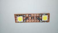 Soldered
 Once all the SMD components are soldered, it's time to solder the cables on. I took about 5cm of ribbon cable and tore it into pieces of 2 wires each. Make sure these little cables are soldered on securely, so that when they're glued into their housing, they won't come loose.
Glue in housing
In the 3D-printed housings, recesses are provided where the printed circuit boards should fit perfectly, if this is not the case, it is best to reduce the size of the printed circuit board with a small file. If any printed circuit boards are still loose, it is best to fix them with a little all-purpose glue.
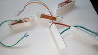 Printed circuit boards glued in housing