









3D Clock
Placed onConnect everything
Now that everything is in place, we can start connecting everything together. Each segment has a GND and a '+', we are going to connect all GNDs of a digit with each other via an "intermediate printed circuit board" (see image below), so not only is the amount of cables to the controller printed circuit board limited, we can now also choose which of the 4 digits is controlled.
All 1-digit wires enter the intermediate circuit board, all GNDs are connected and an 8-core flat cable goes to the controller circuit board.
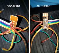 Between circuit board
 Once all 4 of the 'intermediate PCBs' are made, it's time to squeeze on the JST connectors. Make sure you always keep the same order for the 4 digits, with GND all the way to the right.
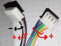 ' - ' = GND ' ' = of the segments
 The cables of the separator (':') also need a connector, for this we use a 2 pin JST connector. The switch and the DC jack also each require a 2 pin JST connector.
Connect to controller circuit board
Now you can connect everything to the controller board:
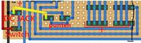
In the end it should now look like this:
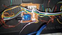 Everything connected to the controller board