3D Clock
Placed onSoldering the controller circuit board
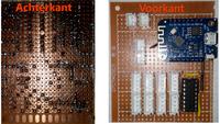
In this step we will make the printed circuit board on which all the steering electronics will be installed. I chose to do this on an experimental printed circuit board, but you can of course also order a pcb from your favorite manufacturer.
The headers you see on the schematic are 4 pin JST connectors, I put the 74HC595 shifter in a 16 pin IC socket.
The yellow colored wires are wire bridges that run along the top of the circuit board.
 Scheme
 If all the components are in place and everything is properly connected together, it should look something like this: