Mp3 player
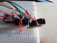
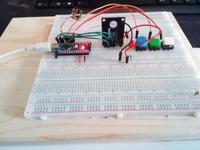
Placed onconnection diagram
The SD card module uses an I²C protocol. This allows us to connect it with 2 wires, 1 for the clock and 1 for the data. The others are used for e.g. detecting an SD, selecting a chip,...
I²C
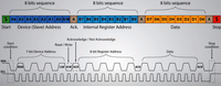
The I²C protocol allows an Arduino to be connected to 128 different modules, which use the same bus. The protocol (serial) is fairly easy. First it sends out an 8-bit number, where the first 7 let it know which module the Arduino wants to communicate with, and a bit to let it know it wants to write or read. Then an acknowledge sequence is sent. Then an 8-bit number is sent to select a register. finally, an 8-bit number is sent or received for the data in that register. These are also distinguished by an acknowledge sequence.
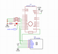
Comments:
DI = MOSI
DO = MISO
CLK = SCK
don't forget to calculate the series resistance of the LED!
(more information can be found in blogabout the series resistor)
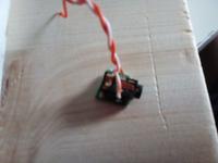
Pin 9
Because pin 9 is an output pin, it is best to connect a headphone jack or speaker here. I definitely advise against using a speaker that has more than 1.5 watts.