Smart meter reader
Placed onIn this blog post I describe how you can easily and for little money make this DSMR logger yourself (DSMR is an acronym for “Dutch Smart Meter Requirements“) can make. When developing the DSMR logger, we want to achieve the following:
With this document in hand and a little Googling you will soon find more information. We are not the first and certainly not the only one who feel the need to read the Smart Meter.
For example, Matthijs Kooijman has written a truly sublime piece of software to parse the telegrams from the meter and store them in bite-sized variables. Of course we will use this library. You can him here to download.
If you do not want to use the DSMR logger PCB, you also need a piece of experimental board.
The total costs are about € 20,-
- The hardware must be simple and cheap to make;
- The firmware of the DSMR logger must be able to be updated “Over The Air”;
- Limited history must be stored and retained internally;
- The DSMR logger must be accessible via an external terminal (telnet);
- The (historical) data must be able to be retrieved from the DSMR logger via FTP for possible external processing;
- The DSMR logger must present the data from the Smart Meter via a browser;
- The data must be able to be requested via a REST API;
- The read data must be easy to process further.
The technology of the Smart Meter
The Smart Meter sends data via the P1 port (RJ12) in the form of a telegram. How the Smart Meter does this and how a telegram is structured is described in this document. Chapter 5 is particularly interesting because it describes how the physical interface is constructed. This shows, among other things, that the Smart Meter must be able to supply 5 volts at 250mA, with a short-term peak current decrease of 300mA. Chapter 6 describes the protocol and the various fields.With this document in hand and a little Googling you will soon find more information. We are not the first and certainly not the only one who feel the need to read the Smart Meter.
For example, Matthijs Kooijman has written a truly sublime piece of software to parse the telegrams from the meter and store them in bite-sized variables. Of course we will use this library. You can him here to download.
Supplies
The most important part of the DSMR logger is the processor. We use an ESP8266 for this because, in addition to being fast and equipped with sufficient memory, it can also communicate via WiFi. To keep costs low, we assume an ESP-01 board (black edition) with 1MB memory. In addition, apart from six resistors and three capacitors (C4 is not really necessary but you can add it if you have problems connecting to your WiFi network), we need an NPN transistor (BC547) and a voltage regulator (MCP1700-3302E). To connect the DSMR logger to the Smart Meter you need an RJ12 plug with a piece of wire. I bought an RJ12 cable on the internet (with two RJ12 male connectors) and cut it in half.If you do not want to use the DSMR logger PCB, you also need a piece of experimental board.
The total costs are about € 20,-
DSMR logger schematic
Below you can see the schematic of the DSMR logger: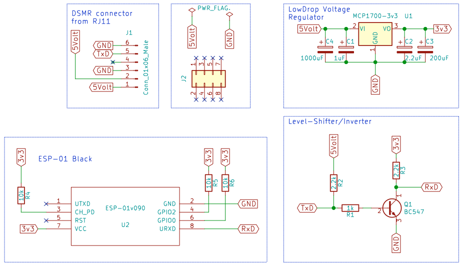 Scheme DSMR Logger
 Roughly speaking, the schematic consists of four parts (the fifth, containing the 5 volts and GND PWR_FLAGs, is technically required by KiCAD but is not actually part of the schematic).
First of all, the connection between the Smart Meter and the DSMR logger. It is easiest to solder the cable directly to the DSMR logger, but you can also use a Molex male connector. You cannot connect Molex connectors “the wrong way round” (that would be annoying because then you connect the 5 volts and Ground from the Smart Meter to Ground and 5 Volts of the DSMR logger respectively, which the ESP-01 will definitely not survive !). The connections on the DSMR logger are the same as on the RJ12 plug (1 is connected to 1, 2 to 2, etc.).
The second part consists of the voltage regulator that converts the 5 volts from the Smart Meter to 3v3 for the ESP-01. According to the data sheet of the ESP-01, it normally uses 80mA and peaks at 200-250mA. The MCP1700 used can supply a maximum of 250mA. Sufficient for this application.
The ESP-01 itself has only 8 connections. Two for the power supply (Vcc and GND), one for communication with the Smart Meter (TxD) and three pins that must be “high” during start-up (CH_PD, GPIO0 and GPIO2). The last two pins (RST and TxD) are not used.
The last circuit part, around the BC547 transistor, has two functions. First of all, it ensures that the 5 volt data from the Smart Meter does not overload the 3.3 volt input of the ESP8266. So it is primarily a Level-Shifter. But it is also an inverter that converts the inverted signal from the Smart Meter into a non-inverted signal for the ESP8266.
The Hardware
As a proof of concept, I soldered a first version of the DSMR logger onto an experimental board.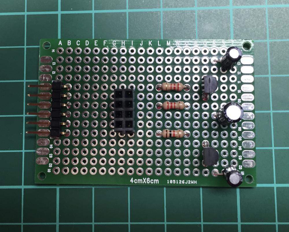 DSRM - Experiment print
 Here you can see the final result connected to the Smart Meter:
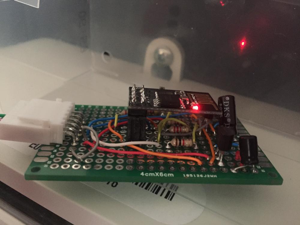 DSRM - Experiment PCB complete
 When it turned out that everything works as planned, I designed a printed circuit board with KiCAD.
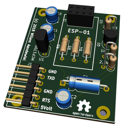 Design DSRM Logger
 Install firmware on the ESP-01
One of the Design Goals is that the firmware “About The Air” (by air) should be able to be put on the DSMR logger. That was also successful, but you will always have to put firmware on the ESP-01 that offers this functionality for the first time. Therefore, you cannot avoid sending the firmware via a wired way to the DSMR logger at least once. In addition, during the development of the software, it happened to me several times that I introduced a bug that made the OTA upload no longer work. Even then, the only way is to send the firmware, without a bug, to the DSMR logger by wire.You need a programmer to program the ESP-01. Another inexpensive solution is to load a special program into an Arduino UNO and then make a number of connections between the Arduino and the ESP-01 board.
The easiest way is to buy an “ESP-01 to USB Adapter” and make a small modification (see my blog post).
The software
In principle, the software is very simple (see the example included with the DMSR library). However, if you want some more options, it quickly becomes quite a project!The DSMR logger uses the following libraries:
These must therefore be installed in your Arduino -IDE environment.
We also use the simple FTP server from David Paiva. This is included as source directly in the DSMRlogger2HTTP sketch (two tabs) and you therefore use quotes (“) instead of less and greater than signs for the include.
We also use the simple FTP server from David Paiva. This is included as source directly in the DSMRlogger2HTTP sketch (two tabs) and you therefore use quotes (“) instead of less and greater than signs for the include.
The special treatment was necessary because I made minor changes to the source and don't want them to be lost on a library update.
The sketch consists of a total of eight tabs. The main program, FTPserver.cpp, FTPserver.h, SPIFFSstuff, TimeStuff, UpdateHTML, WiFiStuff, and menuStuff. You can download the software as a ZIP file from GitHub and then unpack in your Arduino projects folder. If you have git installed on your computer, you can also clone the repository with the command:
It will then create, in the directory where you execute the command (preferably the Arduino projects folder), a folder called “DSMRlogger2HTTP” containing all the code, including a “data” directory to store the ESP file system. -01 (this also contains the file “index.html”).
In pseudo code the program looks like this:
The sketch consists of a total of eight tabs. The main program, FTPserver.cpp, FTPserver.h, SPIFFSstuff, TimeStuff, UpdateHTML, WiFiStuff, and menuStuff. You can download the software as a ZIP file from GitHub and then unpack in your Arduino projects folder. If you have git installed on your computer, you can also clone the repository with the command:
git clone https://github.com/mrWheel/DSMRlogger2HTTP.git
It will then create, in the directory where you execute the command (preferably the Arduino projects folder), a folder called “DSMRlogger2HTTP” containing all the code, including a “data” directory to store the ESP file system. -01 (this also contains the file “index.html”).
In pseudo code the program looks like this:
The main program is repeated endlessly and consists of the following steps:
Start using the DSMRlogger
Before you can use the DSMRlogger you have to upload not only the firmware but also a file system with content to the DSMRlogger. For the sake of convenience, I will assume that you know how to upload the firmware and will limit myself to explaining how to get the filesystem on the DSMRlogger.If not, read my other blog about it making the ArduinoIDE suitable for the ESP8266.
In the Arduino IDE, click on the following menu option:
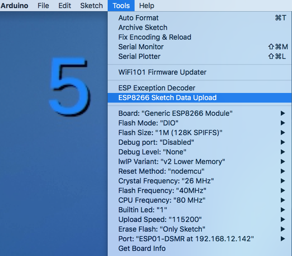 Arduino IDE Data Upload
 All files that are in the “data” directory of this project are now placed in a special part of the ESP-01's memory.
NB! Uploading the file system goes wrong if you have the “Serial Monitor” open!
Now you can connect the DSMRlogger to the Smart Meter, but it does not know the data of your WiFi network. It therefore creates an Access Point (AP) itself to which you must register your computer. You can recognize the AP by the name “ESP01‑DSMR‑xx‑”. When you have connected to the AP, start your browser and go to the as stated in the name of the AP. You will then enter the WiFi configuration menu:
NB! Uploading the file system goes wrong if you have the “Serial Monitor” open!
Now you can connect the DSMRlogger to the Smart Meter, but it does not know the data of your WiFi network. It therefore creates an Access Point (AP) itself to which you must register your computer. You can recognize the AP by the name “ESP01‑DSMR‑xx‑
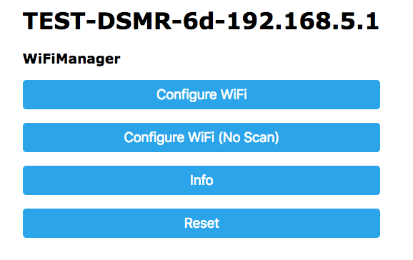 Wi-Fi configuration
 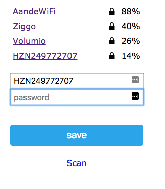 WiFi configuration access point
 Click on the [Configure WiFi] button, after which a page as shown on the right will appear.
On this page, select the WiFi network that belongs to you and enter the password. Then press the [save] button.
If everything went well, you will see the following text:
On this page, select the WiFi network that belongs to you and enter the password. Then press the [save] button.
If everything went well, you will see the following text:
 Confirmation WiFi saved
 The DSMRlogger will now reboot and connect to your WiFi network. During startup you can see from the blue LED what the DSMRlogger is doing
1. 3 slow flashes - initial start
2. 5 fast blinks - connected to WiFi network
3. After that, the blue LED flashes every time a new telegram is processed
If the LED remains on after the first three slow flashes, the DSMRlogger was unable to connect to your WiFi network and will restart its own AP. This may be because your network was temporarily unavailable or difficult to reach or because you did not enter the details for your WiFi network correctly. In that case, the DSMRlogger automatically restarts after a few minutes and tries to reconnect to your WiFi network. This process is repeated until a connection is established or until you re-enter the details of your WiFi network as described above.
The DSMRlogger Web Interface
When the DSMRlogger is connected to your WiFi network you can go to the address with your browser:http://ESP01-DSMR.local/The page below will then appear in your browser. The data you see is automatically refreshed.
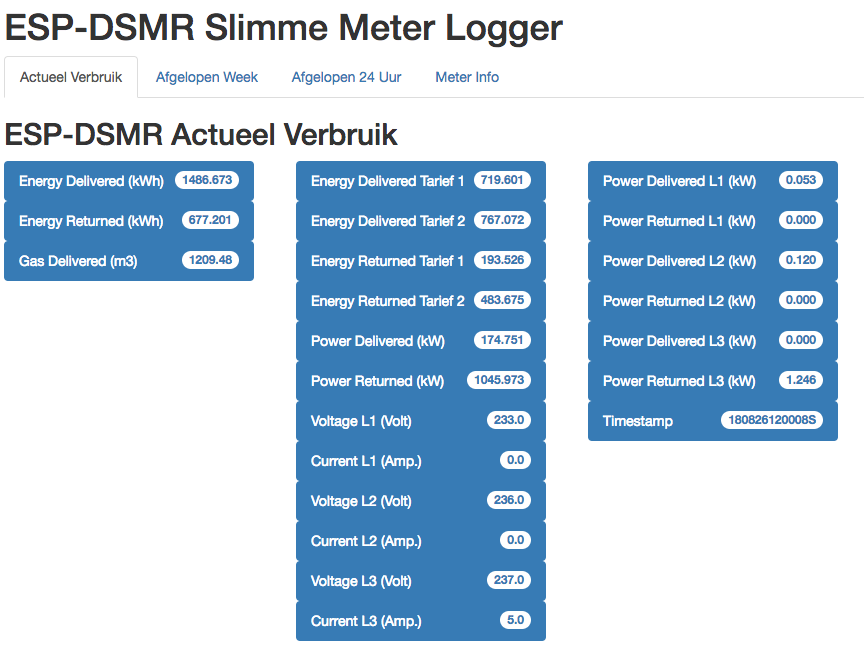 DSMR GUI
 By clicking on the tabs you can view different types of data.
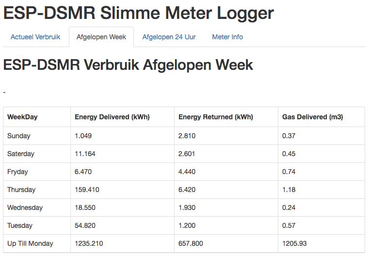 DSMR weekly overview
 telnet session:
To connect to the DSMRlogger via telnet, enter the following command in a terminal window:telnet ESP01-DSMR.localAfter which you can see live what the DSMRlogger is doing. By pressing
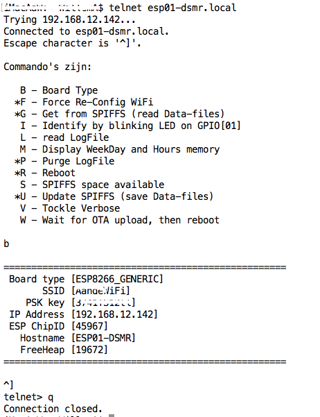 DSMR Telnet
 NB! The DSMRlogger can handle only one active telnet session.
In a follow-up blog post I will show you how to use this data in Home-Assistant.
REST API
If you want to use the data from the Smart Meter from another program, you can retrieve it by requesting this URL:http://ESP01-DSMR.local/getActual.jsonThe DSMRlogger then returns a json string that looks like this:
>
In a follow-up blog post I will show you how to use this data in Home-Assistant.
Update firmware
There comes a time when you want to adjust the firmware of the DSMRlogger to your own insight and needs.It is then annoying to have to walk to the meter cupboard for every adjustment to disconnect the DSMRlogger, remove the ESP-01 from the logger and provide it with new firmware with a programmer of your choice. Fortunately, you don't have to. In the Arduino IDE you cannot only select Serial ports to which the DSMRlogger is connected. The selection menu also contains “Network ports”:
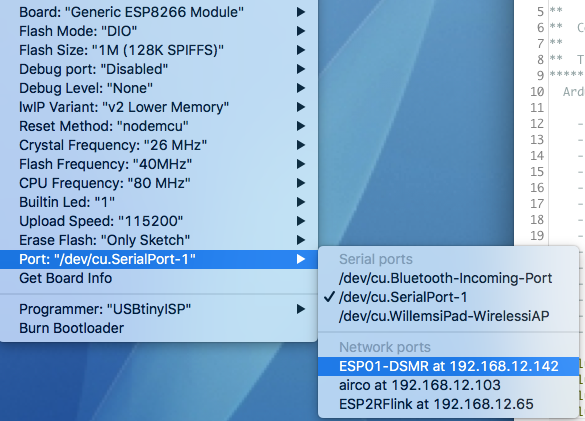 Arduino IDE Port select
 In my case Network port “ESP01‑DSMR at 192.168.12.142” is the network port of my DSMRlogger. By selecting this port and compiling and uploading the new firmware, it will be sent wirelessly to the DSMRlogger (you will notice that this is even faster than with a USB cable!).
Just make sure that the firmware you upload does not contain any annoying bugs. It has happened to me several times that I introduce a bug that causes Over The Air uploading of firmware to stop working (usually the entire DSMRlogger stops working in such a case) so that I still had to go to the meter cupboard...
Just make sure that the firmware you upload does not contain any annoying bugs. It has happened to me several times that I introduce a bug that causes Over The Air uploading of firmware to stop working (usually the entire DSMRlogger stops working in such a case) so that I still had to go to the meter cupboard...
The DSRM logger kit
Version 3 has the same functionality as version 1, but also has some upgrades that make soldering easier.
Opencircuit together with Willem Aandewiel, has put together a kit with PCB and all the necessary parts to build this DSMR logger yourself.
With this kit you can build the DSRM logger yourself on a clearly structured PCB. This not only saves time, but also looks a lot nicer!
With this kit you can build the DSRM logger yourself on a clearly structured PCB. This not only saves time, but also looks a lot nicer!


