Simple ESP-01 Programmer hack
Placed on Opencircuit ESP-01 USB Adapter This ESP-01 Adapter with CH340 USB driver makes it possible to address the ESP-01 Wifi modules easily via the computer. In stock € 2,15
Opencircuit ESP8266 ESP-01S WIFI Module The ESP8266 WiFi module was presented at its introduction as a TTL "Serial to Internet" module. Handy to connect Arduino boards to the internet. It soon turned out that this ESP-01S module and its number of GPIO pins, outwardly carried, bigger brothers (ESP-7, ESP-12, NodeMCU etc. In stock € 3,60
ESP-01 Boot Modes
To put an ESP-01 in firmware upload mode, a number of conditions must be met. In the documentation of the ESP-01 there is this table: ESP01 Boot mode table
 From this you can see that GPIO0 and GPIO2 must both be “high” (3.3volts) for the ESP-01 to work “normally”. The firmware stored in flash memory is then executed. On the ESP-01, GPIO0 and GPIO2 are connected to Vcc through a resistor.
If GPIO0 is made “low” (GND) and you start (or reset) the ESP-01, it waits for new firmware to be offered via the UART (the Serial connection) and puts it in the flash memory.
If GPIO0 is made “low” (GND) and you start (or reset) the ESP-01, it waits for new firmware to be offered via the UART (the Serial connection) and puts it in the flash memory.
 ESP-01 pinout
 USB Adapter Modifications
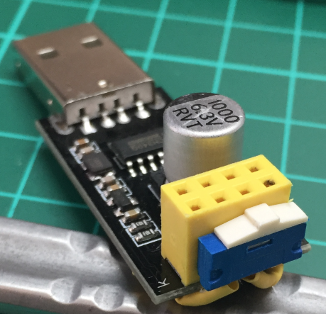
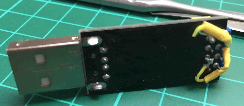
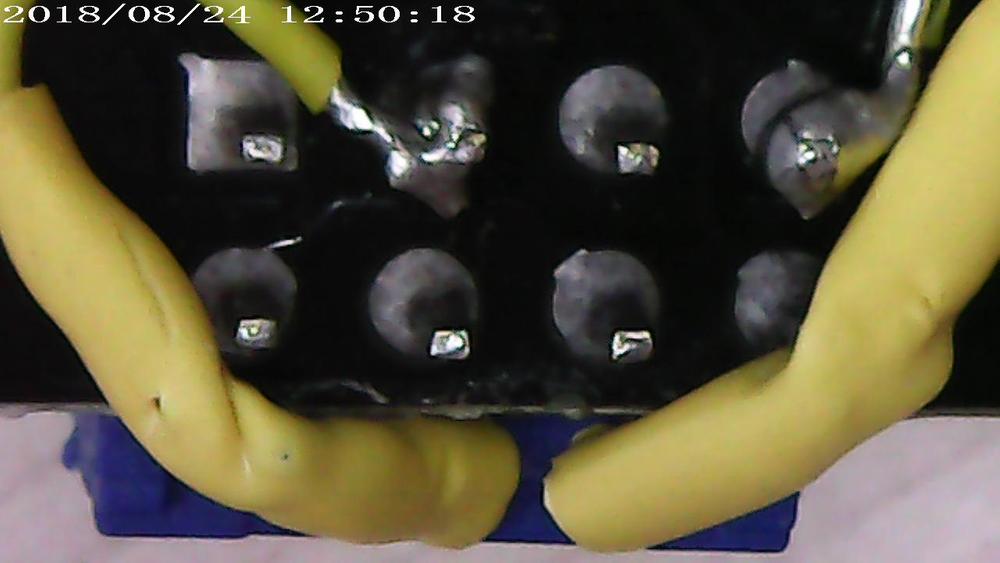
To be able to load firmware to the ESP-01 with the “ESP-01 to USB Adapter” GPIO0 must be connected to GND (see the table above). It is easiest to make a hard connection between GND and GPIO0 on the adapter, but then you can no longer use it as an ESP-01 to USB adapter!So I glued a small slide switch to the adapter and connected two contacts to GPIO0 and GND respectively.
Supplies
Opencircuit Stranded-Core black wire - 26AWG - 2 meter Delivered in 14 to 30 days € 1,35 No longer available Total € 1,35 ESP01 Programmer modification
  ESP01 Programmer modification bottom view
  ESP01 Programmer modification closeup
 How do you use the Programmer?
To provide an ESP-01 with new firmware with this programmer, you have to do things in the right order.1. Insert the ESP-01 into the modified adapter
2. Move the slide switch to the “program” position (GPIO0 connected to GND)
3. Insert the adapter into a USB port on your computer
4. Select the USB port in the Arduino IDE and upload a program
When the upload is complete the ESP-01 will reboot and run the new program. You can now flip the slide switch (GPIO0 no longer connected to GND).
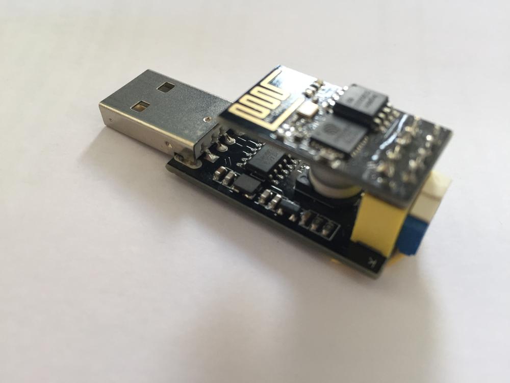
 ESP01 Programmer
 To reprogram the ESP-01, first unplug the adapter from the USB port and then repeat the steps in the same order (you can also unplug the ESP-01 from the adapter and plug it back in). that the ESP-01 restarts!).
If you find it annoying to take the Adapter out of the USB port and put it back in every time, you can put a push button (NO or “normally open”) between the RST pin and GND.
If you find it annoying to take the Adapter out of the USB port and put it back in every time, you can put a push button (NO or “normally open”) between the RST pin and GND.


