Infrared sensor - cold feet
Placed on Infrared panel office
 Infrared heating is radiant heating. The environment is irradiated by infrared heat rays. You feel infrared heating immediately, just like the radiant heat from the sun. Although the radiant heat is stored by furniture, walls and floors, don't expect too much of it. Especially the radiation that directly hits your body, in my case, makes my feet comfortably warm.
All in all a nice solution, but despite the fact that the panel screwed under my desk only consumes 200 watts, it's a shame to leave it on when I'm not at my desk. That's why I made a Motion Sensor that only turns on the panel when I'm sitting at my desk.
All in all a nice solution, but despite the fact that the panel screwed under my desk only consumes 200 watts, it's a shame to leave it on when I'm not at my desk. That's why I made a Motion Sensor that only turns on the panel when I'm sitting at my desk.
Warning
Any circuit that works with mains voltages is inherently dangerous and you should NEVER work with mains voltages unless you know exactly what you are doing.This circuit is purely theoretical and offers no isolation or safety functions!
Therefore, without modification, it is not a safe circuit or has practical applications beyond serving as a proof-of-concept.
Supplies
Opencircuit PIR motion detection module Delivered in 14 to 30 days For detecting movement € 1,85 No longer available The switch for the panel No longer available 5V power supply to power the material No longer available To confirm everything Opencircuit Print terminal block 3 pole 5mm blue - 10 pieces Delivered in 14 to 30 days € 1,50 Total € 3,35Not necessary, but handy
330 ohm resistor and a red + green LED for status indication.The modules used
By making use of ready-made modules building this motion sensor is quite easy.Hi-Link HLK-5M05
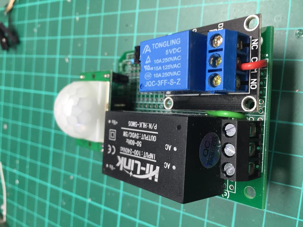
The Hi-Link HLK-5M05 is a switching power supply that converts the mains voltage to a stable 5 volt DC current required for the PIR and relay modules.
 Hi-Link HLK-5M05
 PIR module
The PIR module is a completely independent unit that, when detecting movement (thermal image), activates the Signal pin “high” and after some time (if no change in the thermal image occurs) the Signal pin again “lowmakes.
There are two adjustment potentiometers with which the sensitivityand the durationof keeping the Signal pin high can be set. The “high” time is adjustable from a few seconds to a few minutes.
The unit I have seems to never go “low” at all after about one-third of the settings, but it is possible that I just have a module that is not functioning properly.
 PIR module settings
  PIR module pinout
  PIR sensor module
 Relay module
The relay module has all the electronics on board to switch high voltages in a relatively safe way (but keep the warning in mind. Mains power remains dangerous!).
The screw connector has three terminals. The middle one must be connected directly to the mains phase. At the top connection in the picture, the consumer are being connected. With a “high” signal, it will be connected to the phase of the mains (and thus supply the connected device with voltage).
 Relay module
  Relay module bottom
Connecting the dots
The modules must be connected as shown below. Connection diagram
 It works easiest if you solder the connections to the bottom of the experiment board. The gray wire is the "edge earth" (for when you use a plug and consumer with earthed edge). The two LEDs are 'extra' and not necessary for operation. For this I soldered and connected two female headers (2-pin) on the experiment board. I connected the LEDs via two wires with 2-pin mail headers so that I could glue them to the lid of the housing. Don't forget the resistor in series with the LED that will be connected to +Vo and -Vo!
Before you connect the motion sensor to the mains, place the whole thing in one solid housing (this is necessary and must be put together yourself).
Before you connect the motion sensor to the mains, place the whole thing in one solid housing (this is necessary and must be put together yourself).
 PIR sensor A
  PIR sensor B
  PIR sensor C
  PIR sensor in housing


