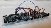
HC-SR04 Ultrasonic sensors on an Arduino Uno board
Placed onHC-SR04 Ultrasonic sensors on an Arduino Uno board
Reading in an HC-SR04 sensor on an Arduino board is relatively easy, but what if you want to read in multiple sensors? How do you do that in an efficient way? This article explains using an example how you can efficiently read in 4 sensors, and how you can further expand this to multiple sensors.
 Build 4x HC-SR04 ultrasonic sensors on an Arduino Uno board
 What is an HC-SR04
The HC-SR04 is a break-out board with ultrasonic sensors. On this sign are two cylindrical objects, one of which is marked with the letter “T”, which stands for “Transmitter”, which means “sender”, while the other is marked with the letter “R” for “Receiver”, which means “ receiver”. The transmitter sends out an ultrasonic sound wave, and the receiver “listens” for this sound wave to collide with an object and be reflected back. The time that elapses between transmission and reception indicates how far that object is from the sensor. Bats, dolphins, whales and sonar in ships work on a similar principle, and this principle is often referred to as "echo location".
 HC-SR04 breakout board
 Can you hear an ultrasonic sound wave
Unless you have your dog's ears, you cannot hear ultrasonic sound waves. The HC-SR04 uses a sound wave with a frequency of 40kHz, while a human ear can only hear 16kHz, and younger people can hear up to 20-22kHz. Far below the frequency of an ultrasonic sound wave.
Furthermore, an ultrasonic sound wave is not a radio wave (like the waves from a smartphone), and is completely harmless to health.
How does the HC-SR04 work
As mentioned earlier, the HC-SR04 emits an ultrasonic sound, which collides with an object and returns to the sensor. The sensor counts the time that elapses between sending and receiving this signal. If you know the speed of sound, you can calculate the distance between the sensor and the object. Of course, sound does not travel infinitely far and because the sound wave of the sensor is relatively weak, the measuring range is also quite limited. The HC-SR04 can measure distances up to approximately 400cm (4m). The “viewing angle” or “measuring angle” of the sensor is also not infinite. Objects that fall outside an angle of 15° cannot be detected by the sensor. That is why it is sometimes interesting to use several sensors, which you place in a circle, for example. In this way you can increase the measuring angle.
Read the sensor
To read the HC-SR04 you need to generate a start pulse on the “trigger” pin of the sensor. The response from the sensor will appear on its “echo” pin. Both pins are connected to digital I/O pins of the Arduino .
Trigger
To generate a start pulse, you must complete the following steps
- Trigger pin must be low for at least 2µs (micro seconds).
- Trigger pin must then be high for 10µs
- Trigger pin back low
With the Arduino you can easily do this with the following piece of code:
HC-SR04 "Trigger"
Echo
The response that appears on the echo pin of the sensor is a pulse whose duration is equal to the time between the transmission and reception of the ultrasonic sound wave, expressed in µs (micro seconds). One possibility to measure such a pulse on the Arduino is with the function “pulseIn”:
Meet "echo"
Calculate distance
Of course, after all this you only know the travel time of the sound wave, but this does not mean you know the distance. Fortunately, the speed of sound is known, and the distance can be calculated with this:
distance [m] = speed_sound [m/s] * time [s]
and the speed of sound is 343m/s, so
distance [m] = 343 [m/s] * time [s]
However, the HC-SR04 gives the time in µs, and for easy counting the distance in cm would be more convenient, but with some calculations the formula can be adjusted to
distance [cm] = 0.0343 [cm/µs] * time [µs]
The only problem that remains now is that the time indicated by the HC-SR04 is the time the pulse travels back AND forth, and since only the distance to the object is useful, you just have to divide the time by 2 :
distance = 0.0343 * (time/2)
Simple test setup
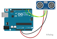
A quick test set-up to test the operation of the HC-SR04 can be realized with the following scheme and code:
 One HC-SR04 sensor on the Arduino Uno
 Eenvoudige code voor het testen van een HC-SR04 op een Arduino Uno
Multi HC-SR04
From here it gets a little bit more difficult. Because the function “pulseIn” pauses the code, and is not sufficiently precise, the extended code uses port registers and interrupts. If this sounds unfamiliar, you can find more information on the website of the author of this article: http://kunoichi.be/projects/
(the website is only available in English)
Multiple sensors
To use multiple sensors, you can proceed in three ways:
- separate trigger per sensor; separate echo per sensor
- common trigger; separate echo per sensor
- separate trigger per sensor; common echo
separate trigger per sensor; separate echo per sensor
The easiest way, and least efficient, is to connect each trigger and echo pin of each sensor to a separate pin on the Arduino .
In other words, 2 pins on the Arduino per sensor.
common trigger; separate echo per sensor
Another way is to connect all the triggers of the sensors and connect them to 1 pin on the Arduino . The echo pin of each sensor must then be connected to a separate pin on the Arduino . The advantage, as well as the disadvantage, is that all sensors send their response at the same time. There is a possibility that the sensors will interfere with each other, and you also need a separate interrupt pin for each sensor (the Arduino Uno only has 2). You could use regular pins, but then the accuracy would drop a bit.
separate trigger per sensor; common echo
If super fast reading is not necessary, you can still achieve very good accuracy with the third method, and you do not have the disadvantage that the sensors will interfere with each other.
Each trigger pin of the sensor is connected separately to the Arduino , and all echo pins are connected to 1 single Arduino pin. This pin is called an interrupt pin. Because you decide which trigger is controlled, you know which sensor's response to the common echo pin is.
This is the most efficient way to use multiple HC-SR04 sensors on a single Arduino board.
Scheme
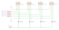
A small disadvantage with the common echo pin method is that the sensors can interfere with each other on this pin, but that can be easily remedied by using diodes. The structure of the system is as follows:
 Scheme 4x HC-SR04 sensors on common echo pin
 The time diagram shows how the signals progress.
- The start pulse (trigger) for sensor 4 is sent.
- This responds to the echo pin.
- The start pulse (trigger) for sensor 3 is sent.
- It responds to the same echo pin, but since the start pulse is monitored, it is known from which sensor the response comes.
- The start pulse (trigger) for sensor 2 is sent.
- ...
- Repeat from step 1
The rest is literally copy/paste, and can easily be extended to multiple (or fewer) sensors in this way.
 Time chart 4 triggers, 1 echo
 The code for reading the sensors is as follows:
(Explanation of the code is provided via comment fields in the code itself)
Uitbreidbare code voor het uitlezen van meerdere sensoren
Although this is not the fastest method, and with long distances and many sensors the lead time can be relatively high, this method offers some advantages
- only 1 interrupt pin needed
- very easily expandable
- sensors do not interfere with each other
- optimal use of number of sensors versus available I/O pins
Note regarding power supply
Because the 5V pin on the Arduino can supply limited current, it is recommended to provide an extra 5V DC power supply to power the sensors. For this reason, a “Breadbard Power Supply” is included in the component list, but in essence this can be replaced by any 5V DC power source.
Components
The components used in this project are all available at Opencircuit, and are listed below:


