Breadboards for beginners: Tips & Tricks for successful projects
Placed onWelcome to our breadboard blog, the perfect place to start your electronic adventure. Whether you're a student, hobbyist, or aspiring inventor, this article will help you understand the basics of breadboarding and get you excited to start your own projects. Let's start!
What is a breadboard?
A breadboard is a rectangular plastic board with small holes in it that allows you to build electronic circuits without soldering. It's a great way to quickly and easily experiment with electronic components such as resistors, LEDs, switches and more. Their versatility and ease of use make breadboards indispensable for beginners and experienced electronics enthusiasts alike.
“Breadboards are designed to eliminate the need for soldering when experimenting with electronic circuits.”
- In stock Opencircuit Breadboard white 400 points € 1,10
- In stock Opencircuit Breadboard transparent 830 points € 2,10
- 10 pieces In stock Opencircuit Breadboard Mini set - 10 stuks € 5,55
- Velleman Solderless breadboard - 830 holes + jumper wires - 140 pcs € 10,50
- Opencircuit Breadboard 830 points - white € 1,20
- Velleman High quality breadboard - 1680 insertion points € 18,70
- DFRobot Multi-color Block Building Breadboard Kit € 12,25
The fascinating history of the breadboard
The story of the breadboard begins in the 1960s and 1970s, when electronics experiments became increasingly popular. At the time, there were no standardized solutions for quick and easy circuit testing, forcing hobbyists and engineers to resort to creative solutions. A popular method was to use wooden boards (literally called "breadboards") to which nails or screws were attached to make connections to electronic components. Hence the name "breadboard"!
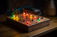 A wooden shelf with electronics
 The first true breadboards as we know them today were introduced in the early 1970s and were made of white plastic with a grid of holes into which components could be inserted. These breadboards made it easier than ever for hobbyists and engineers to quickly and easily build, test, and modify various circuits without soldering. Soon the breadboard became an indispensable tool for both beginners and experienced electronics enthusiasts around the world.
Over the years, breadboards have evolved and adapted to the changing needs of the electronics community. Today they are available in a variety of sizes, materials and colours, making them suitable for a wide variety of projects and applications. It's fascinating to see how a simple tool, originally inspired by a wooden plank, has evolved into an essential part of the modern electronics world!
Connections inside a breadboard
When working with breadboards, it's important to know how the connections inside work. Breadboards consist of two main parts:
- The component zone (green): The component zone is usually located in the center of the breadboard and consists of horizontal rows of holes. Each row is split into two separate groups with a vertical gap between them, which helps prevent short circuits between components. The holes within one group are electrically connected, making it easy to connect components by plugging their legs into the same group.
- The power rails (red / blue): The power rails are on the sides of the breadboard and run vertically. They are usually marked with '+' and '-' symbols to indicate the positive and negative terminals. The holes in each power rail are connected together, making it easy to distribute power and ground to the different parts of your circuit.
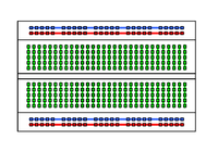 Internal connections breadboard
 The gap in the middle of the breadboard, which splits the horizontal rows into two groups, is specially designed to accommodate integrated circuits (ICs) and prevent shorting between components. This allows you to safely and easily place ICs on the breadboard.
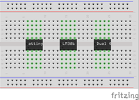 A breadboard with ICs
 The power rails on the sides of the breadboard make it easy to connect external power sources, such as batteries or an Arduino . By connecting the positive and negative terminals to the correct rails, you can effortlessly supply voltage to all parts of your circuit.
 A breadboard with an Arduino and batteries
 Tips and tricks to get the most out of your breadboard
If you're starting to use breadboards for your electronics projects, there are some helpful tips and tricks that can help you optimize your breadboarding experience. In the following paragraphs we will introduce you to these smart techniques and best practices. Whether you're a beginner just getting into breadboarding, or an experienced maker looking for new ideas to further improve your skills, these tips and tricks are sure to help you get the most out of your breadboard and keep your projects running smoothly. and run successfully. So let's get started and master the art of effective breadboarding!
Provide an uncluttered workspace
A clutter-free and organized workspace is essential when working with breadboards and electronic projects. While it is by far the most ignored tip (we know that a chaotic desk sometimes seems unavoidable), it will help you work more efficiently, reduce errors, and keep your concentration while building and testing your circuits. Plus, you'll feel like you can take on the world when your desk is tidy - or at least your breadboard projects!
Here are some tips for creating and maintaining an uncluttered workspace:
- Make sure you have enough space on your work surface to spread out your breadboard, components, tools, and other supplies. This makes it easier to access everything you need and prevents unnecessary searching or clutter.
- Organize your components and tools storage boxes, drawers or special organizers. This helps you find what you need quickly and keeps your workspace neat and organized.
- Keep a notebook or digital document handy to jot down your circuits so you can easily keep track of what you've done and what you still need to do.
- Clean up your workspace regularly and throw away unnecessary items. This helps to reduce clutter and ensures that your workspace is always ready for your next breadboard project.
 Time to clean up
 Check the polarity of components
When working with breadboards and electronic components, it is important to pay attention to the polarity of certain components, such as diodes and electrolytic capacitors. These components have a specific positive (anode) and negative (cathode) side, and it is crucial that they are connected correctly to avoid misplacing them, which could lead to failure or even damage to the components.
When working with electronic components such as diodes and electrolytic capacitors it is important to be able to identify the anode (positive side) and the cathode (negative side). Here are some easy ways to identify the anode and cathode:
Diodes:
- The cathode is usually indicated by a dash or band on the diode housing. The anode / + is the unmarked side.
- The leg of the cathode / - is usually shorter than that of the anode.
Electrolytic capacitors:
- The positive side (anode / +) has a longer leg, while the negative side (cathode / -) has a shorter leg.
- The capacitor housing often has a dashed mark or a minus (-) symbol on the cathode side.
Cut or bend the legs of your components to the correct length
An important aspect of working with breadboards is ensuring good connections between the components and the breadboard itself. To achieve this, it is critical to cut or bend the legs of your components to the correct length before placing them on the breadboard.
Legs that are too long can cause unwanted contact with other rows or components on the breadboard, causing short circuits and unpredictable circuit behavior. On the other hand, legs that are too short can make it difficult to get a reliable connection to the breadboard, causing the component to come loose or make a bad contact.
To ensure the proper length of the legs, you can use wire cutters to cut off any excess material. Be careful not to cut the legs too close to the component housing, as this may affect or even damage the functionality of the component.
When bending the legs, especially of resistors, a resistor bending tool can be a handy help. This tool provides an even bend so that the legs fit snugly into the breadboard holes without applying too much pressure. This helps to ensure a reliable electrical connection and reduces the risk of the legs coming loose while working on the project.
Plan your circuit on paper or use software
Before you start building your circuit on the breadboard, it's a good idea to draw your design on paper or design it using simulation software. This step can save you a lot of time, effort, and frustration by detecting potential problems and errors before you place the components on the breadboard.
There are several software programs available that can help you design and simulate your circuits. Here are some popular options to consider:
- Fritzing: Fritzing is an open-source software package developed specifically for breadboard circuit design. With Fritzing you can easily design and visualize circuits, and even create circuit board designs for future projects.
- Tinkercad Circuits: Tinkercad Circuits is a web-based simulation tool that allows you to build and test breadboard circuits in a virtual environment. It has a simple interface and includes built-in components such as Arduino and sensors.
- LTspice: LTspice is a powerful free analog circuit simulation software. It allows you to simulate and analyze complex circuits to optimize performance before building them on a breadboard.
Use a breadboard power supply
Use a logical order when placing components
When working with breadboards, it is important to follow a logical order when placing components. This helps keep your circuit organized and uncluttered, making it easier to understand, modify, and debug. A good approach is to start by connecting the power supply and then place the remaining components.
By connecting the power supply first, you lay a solid foundation for your circuit. This ensures that all components are supplied with the necessary power, so that your circuit can work correctly and safely. After the power supply is connected, you can concentrate on placing the remaining components in a logical order.
It can be helpful to start by placing the most important components, such as microcontrollers, sensors, or integrated circuits. This helps you to get a clear picture of how the circuit is built and where to place the passive components, such as resistors, capacitors and diodes.
After the main components have been placed, you can continue adding the passive components in a logical order. This usually means working from the input of the circuit to the output, keeping the signal path clear and organized.
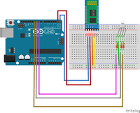 A bluetooth RGB LED on a breadboard
 Breadboard-friendly components
The use of breadboard-friendly components, such as headers and cables, can greatly facilitate connecting modules and sensors to your breadboard. These specially designed components usually have legs that fit perfectly into the holes of the breadboard, making them easy to install without additional modifications or tools.
In addition, there are breadboard-friendly cables, such as jumper wires, that make it easier to connect sensors, switches, and other components to your breadboard. These cables have pins or connectors on both ends, making them easy to connect to the breadboard and components.
Another tip for working with breadboards is to use color-coded jumpers. Using different colors for different types of connections, such as red for power, black for ground, and other colors for signal wires, makes it easier to track your circuit and spot any errors. This can be especially useful on more complex projects, where keeping track of all connections can be a challenge.
Breadboards: temporary; PCBs: permanent
Solderless breadboards are an excellent choice for temporary projects, prototypes and experiments. They enable you to quickly and easily build electronic circuits without having to solder. This makes it easy to add, remove or change components as you work on your project. However, for more permanent applications and projects requiring higher levels of reliability and durability, printed circuit boards (PCBs) used.
Printed circuit boards are designed to mount electronic components on a rigid substrate, usually made of fiberglass or some other insulating material. The components are soldered in place, ensuring a solid and reliable electrical connection. PCBs can also be designed with specific traces and paths to optimize the flow of electricity between components and reduce the chance of interference and other problems.
Using a PCB instead of a solderless breadboard has several advantages. First, it offers higher reliability, as soldered connections are much less prone to loosening or interrupting. In addition, PCBs are better suited for projects that are subject to vibration, humidity, or other environmental factors that can affect a breadboard's performance.
Tip: Adafruit 's Perma-Proto PCBs share the standard breadboard layout, making it easy to convert your breadboard projects into permanent solutions.
Time to explore the wonderful world of breadboards
There you have it, future breadboard masters! With these helpful tips and tricks mastered, you'll be ready to explore the wonderful world of breadboards and enjoy the endless possibilities they offer. Don't be afraid to experiment, because in the end we all learn the most by doing (and occasionally making some mistakes).
Don't forget to have fun building your creations! So sit back, get your workspace ready and start making your electronic dreams a reality. Good luck and above all have fun!


