Arduino Uno as 74HC4051 (MUX/DEMUX) tester
Placed on74HC4051 testing
The 74HC4051 is a multiplexer/demultiplexer IC. To test this, the Arduino Uno can be used with two 74HC4051 ICs. The first IC acts as a multiplexer, the second as a demultiplexer.
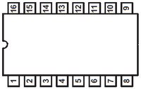
pinout
 | For correct pin numbering, keep the notch in the IC to the left! The pin on the bottom left is pin number 1. Continue counting to the right to pin number 8. The pin on the top right is pin number 9. Now continue counting to the left up to and including pin number 16. The pin configuration of the 74HC4051 is as follows: |
| Pin | Label | Function |
| 1 | A4 | Channel in/out |
| 2 | A6 | Channel in/out |
| 3 | A | Common in/out |
| 4 | A7 | Channel in/out |
| 5 | A5 | Channel in/out |
| 6 | ~E | Enable (negative) |
| 7 | Cattle | Negative power supply |
| 8 | GND | Ground (0V) |
| 9 | Vcc | Power supply (5Vdc) |
| 10 | A2 | Channel in/out |
| 11 | A1 | Channel in/out |
| 12 | A0 | Channel in/out |
| 13 | A3 | Channel in/out |
| 14 | S0 | Address line bit 0 |
| 15 | S1 | Address line bit 1 |
| 16 | S2 | Address line bit 2 |
Digital testing
Although the 74HC4051 is an analog MUX/DEMUX, it cannot be analog tested with the Arduino Uno as it has no analog outputs (DAC). Later in this article, it is described how this can be achieved with a DAC breakout board. To test digitally, only the Arduino board and 2 ICs are needed.
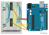
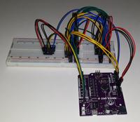
Connect
Set pin 16 (Vcc) of both ICs to 5VDC; pin 8 (GND) at 0V.
Connect pins 6 (~E) and 7 (Vee) of both ICs to GND as well.
Connect the following pins of both ICs: 1,2,4,5,15,16,13,12 (A0..A7).
Connect pins 11 (S0) of both ICs to the Arduino board on A0.
Connect pin 12 (S1) of both ICs to the Arduino board on A1.
Connect pins 13 (S2) of both ICs to the Arduino board on A2.
From IC 1, connect pin 3 (A) to the Arduino board on A4.
From IC 2, connect pin 3 (A) to the Arduino board on A5.

Arduino code
Use following code for the Arduino
Test 74HC4051 MUX/DEMUX met Arduino Uno
The result is something in this genre:
Components
The components for this test:
Component list
Opencircuit 74HC4051 multiplexer - 5 pcs Delivered in 14 to 30 days (sold per 5) € 3,45 Opencircuit Breadboard white 400 points In stock € 1,10 Opencircuit Male-Male jumper set 65 stuks Delivered in 14 to 30 days € 1,65 Total € 6,20In the same way you can test the version on the breakout board
Analog testing
To test analog you need a DAC. The Arduino Uno does not have this as standard, but with the help of the " Adafruit MCP4725 (12bit DAC)" breakout board, you can possibly achieve this.
Connect
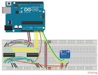
The connection must then be adjusted:
Put pin 3 (A) of IC 1 on the output of the MCP4725 (VOU) (instead of on A5)
Put pin 3 (A) of IC 2 on pin A3 of the Arduino board (instead of on A4).
Pins A4 (SCA) and A5 (SCL) of the Arduino board must be connected to SDA and SCL of the MCP4725.
Also connect VDD and GND of the MCP4725 board to 5V and GND respectively.
Connect pin A0 of the MCP4725 to GND to select I2C address 0x62.
(Alternative: Select A0 at 5V at address 0x63.)

Adafruit Libraries
To control the Adafruit MCP4725 DAC, it is recommended to download the corresponding library from Adafruit .
You can find these at Github.
The code for the analog testing is then as follows:
Test 74HC4051 MUX/DEMUX met Arduino Uno en DAC
The result on the serial monitor is in this genre:
There will occasionally be “errors” due to rounding and inaccuracies. For example, you can see that 2.89V is not equal to 2.88V. However, in combination with all other successful results, you can assume that the MUX/DEMUX works perfectly.


