


Never enough GPIO pins on a Micro Processor
Placed onSomehow, no matter which microprocessor I choose, I run out of GPIO pins for the project needs or for what I want to do.
So for a recent project I switched from the ESP8266 to the ESP32 which has a lot more GPIO pins than its predecessor.. but still not enough for the project I'm working on.
To end this run for GPIO pins once and for all, I decided I needed a cheap expansion board that could be configured for switches (input) and LEDs or other things (output). And while I was at it, I thought some extra logic would be nice.
So what I came up with is an I2C board with eight GPIO pins that are freely configurable for input or output (I call the GPIO pins "Slots").
The expansion board is ideal for use on a solderless breadboard. The schematic can later be incorporated into the overall hardware design.
 ADW0720 Type 2
 A Slot configured for input will probably be used for switches and then it would be great if we could distinguish between pressing the button and releasing it (quick release, middle release and long release). In the code on the main processor you can just say:
Slots configured for output become a "shoot and forget" type of slot. That is, you can tell the Slot to be HIGH or LOW as with the digitalWrite() function in the Arduino IDE. But you can also say: goes HIGH for 2500 ms and then goes LOW again. In your main program you don't have to write the code to wait 2500 ms and then make the GPIO pin LOW.
You can also tell the Lock to flash with an on time and an off time and, if you want, a duration. For example:
The Lock flashes at 500ms on, 1000ms off for a period of 10 seconds (10000ms) and then stops flashing.
Similar to the example above, but now the Lock will blink forever (or until you tell it to do something else);
The hardware is designed around an ATtiny841 microcontroller. Communication is via the I2C bus (two wires, SCL and SDA).
You can run the boards at 5Volt or 3.3Volt depending on your needs (mainly the voltage the main processor uses) but you can't wire 5Volt and 3.3Volt systems together without some extra logic (level shifters for the SDA and SCL lines).
 ADW0720 ATtiny841
 To control the ADW0720 boards I developed a library with simple functions.
Every I2C device has an address in the range of 1 to 127 (decimal). The default address for the ADW0720 boards is 0x18 (24 decimal) but you can change this to whatever you want with the following code:
The second line stores this newAddress into EEPROM and from then on it is newAddress the address for this module.
By giving each ADW0720 board a unique address, you can control multiple ADW0720 boards using just the two I2C lines!
I have designed two types of ADW0720 boards that are ready to use. The Type-1 board has 4 tactile switches and 4 LEDs, the Type-2 board has 8 LEDs but no switches.
") ADW0720 Type 1 (4 LEDs, 4 Switches)
ADW0720 Type 1 (4 LEDs, 4 Switches) ") ADW0720 Type-2 (8 LEDs, no Switches)
ADW0720 Type-2 (8 LEDs, no Switches)
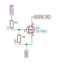
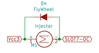
Instead of the LEDs, it is also possible to drive an N-channel MOSFET (such as the 2N7000 or 2N7002) as a switch to drive larger loads such as buzzers, relays or motors.
You can find the library and code for the ATtiny841-I2C slave at github. There you will also find the documentation for the library.
The library comes with two example sketches. The first is to show what the ADW0720 boards can do (show-of) and the second example (I2C_ADW0720_Configurator) shows the more advanced usage.
For example, with the second example you can set the function (input or output) of the Slots and you can set the I2C address of the ADW0720 so that you don't have to do that in your main program.
 Schematic of the ADW0720 Type-1 board
 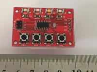 ADW0720 Type-2 board
  Helper functions from the library