









DONOFF iot light dimmer
Placed onMOSFET control circuit
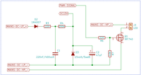
This is the most important part of the DONOFF electronics. D2, D3, R3, R4, and C2 function as a low-power 15 Volt power supply to control the gate of Q1. The MOSFET's gate is normally pulled to GND by R7 (MOSFET switch "open" - LED light is Off). To close the MOSFET, the optocoupler needs to pull the gate to 15 Volts (MOSFET switch "closed" - LED light is On). The Optocoupler (U1), R6, and R7 use about 2.2mA (15v/(150+6800)). C2 acts as an energy buffer and D2 ensures energy doesn't leak if the rectified voltage (MAINS-DC) drops below 15 Volts. Together with the Zener Diode D3, the control voltage for the gate of Q1 stays between 12.5 - 15 Volts (Q1 is fully closed when the gate voltage Vgs is > 10 Volts).
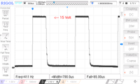 Gate Fall Time
 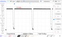 Gate Fall time Max.
 The voltage is normally 15 Volts but drops to 13 Volts at 100% PWM (the MOSFET is then constantly closed)
The current flowing through R4 is also about 2.2mA, which means that R4 has to convert about 0.7 Watt (I2 * R = 4.8 * 150) into heat. The temperature of R4 becomes a maximum of 15°C higher than the ambient temperature. It is therefore necessary that a 400 Volt 2 Watt resistor is used for R4 (a bit over dimensioned).
Resistor R6 limits the current through the optocoupler and the gate of Q1.
C1 filters the “MAINS” DC voltage.
The current flowing through R4 is also about 2.2mA, which means that R4 has to convert about 0.7 Watt (I2 * R = 4.8 * 150) into heat. The temperature of R4 becomes a maximum of 15°C higher than the ambient temperature. It is therefore necessary that a 400 Volt 2 Watt resistor is used for R4 (a bit over dimensioned).
Resistor R6 limits the current through the optocoupler and the gate of Q1.
C1 filters the “MAINS” DC voltage.